
A few months ago, we received an RFQ for a batch of aluminum electronic housings from a European customer.
At first glance, everything seemed ready for production.
The customer provided a PDF drawing, a 3D model, and a clear quantity requirement. However, during our engineering review, we identified several issues:
- Two hole locations were not fully defined
- Surface finish requirements were missing
- Tight tolerances had been applied to nearly every dimension
None of these problems affected the part’s functionality. Yet they significantly increased engineering review time and machining costs.
The customer originally expected a unit price of around $8 per part. After evaluating the drawing requirements, the actual machining cost was much higher than anticipated.
The design itself wasn’t the problem.
The drawing was.
After reviewing thousands of CNC machining drawings over the years, we’ve found that the same mistakes appear repeatedly. Most are easy to fix, but they can increase manufacturing costs, delay production, and create unnecessary communication between customers and suppliers.
In this guide, we’ll explore the most common CNC drawing mistakes engineers make and explain how to avoid them before sending your next RFQ.
Why Drawing Quality Directly Affects Machining Cost

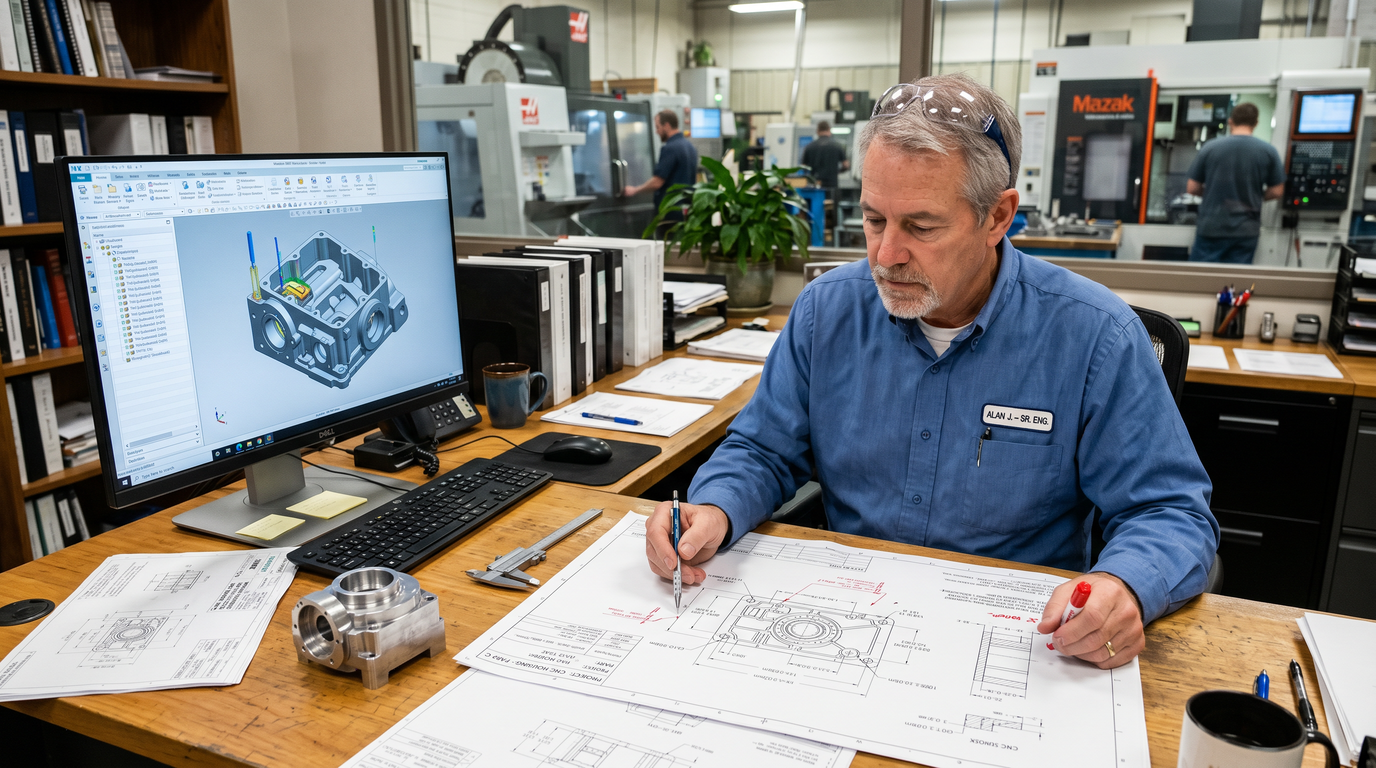
A CNC drawing is much more than a document showing dimensions. It serves as the primary communication tool between the designer and the manufacturer.
When information is unclear or incomplete, suppliers must spend additional time reviewing, clarifying, and sometimes redesigning manufacturing processes before production can begin.
The table below shows how common drawing issues affect manufacturing.
| Drawing Issue | Impact on Manufacturing | Result |
|---|---|---|
| Missing dimensions | Additional engineering review | Longer quotation time |
| Tight tolerances | Extra machining operations | Higher cost |
| Missing material grade | RFQ clarification required | Delayed production |
| No surface finish callout | Rework risk | Quality disputes |
| Missing STEP file | Manual programming required | Increased engineering cost |
| Incomplete thread information | Machining uncertainty | Production delays |
Many engineers focus heavily on part geometry but underestimate how much drawing quality influences project success.
Mistake #1: Missing Critical Dimensions
One of the most common issues we encounter is incomplete dimensioning.
A drawing may appear complete, but a few missing dimensions can make manufacturing impossible.
Incomplete Feature Definitions
Recently, we reviewed a stainless steel bracket drawing containing twelve dimensions.
The overall size was clearly specified, but two mounting hole locations were missing reference dimensions.
Three engineers reviewed the drawing and reached three different interpretations.
The project was delayed nearly a week while clarification was requested.
Common examples include:
- Undefined hole locations
- Missing slot widths
- Missing pocket depths
- Undefined chamfers
- Missing radii
If a machinist cannot determine a feature’s exact size or location, production cannot proceed confidently.
Poor Datum Selection
Another common mistake is dimensioning features from multiple unrelated references.
Without a clear datum structure, inspection results may vary depending on who measures the part.
Good datum selection improves manufacturing consistency and inspection repeatability.
Mistake #2: Over-Tolerancing Every Dimension
This is probably the most expensive drawing mistake engineers make.
Many drawings specify unnecessarily tight tolerances on every dimension, even when most features do not affect functionality.
Applying Aerospace Tolerances to Commercial Parts
It’s not unusual to see drawings where every dimension carries a tolerance of:
±0.01 mm
even though the part is intended for a simple industrial application.
This creates unnecessary manufacturing challenges.
The Real Cost of Tight Tolerances
Tighter tolerances require:
- Additional machine setup
- Slower cutting speeds
- More inspection time
- Specialized measuring equipment
- Increased scrap risk
The cost impact can be significant.
Typical Tolerance Cost Comparison
| Tolerance | Relative Manufacturing Cost |
|---|---|
| ±0.10 mm | Low |
| ±0.05 mm | Standard |
| ±0.02 mm | High |
| ±0.01 mm | Very High |
| ±0.005 mm | Aerospace Grade |
In many projects, relaxing non-critical tolerances can reduce machining costs by 15–30% without affecting product performance.
Mistake #3: Incomplete Material Specifications
Many RFQs simply specify:
“Aluminum”
or
“Stainless Steel”
without identifying the exact material grade.
Unfortunately, this is not enough information for accurate quoting.
Material Grade Matters
Different grades have different properties, costs, and machining characteristics.
Common Material Specification Mistakes
| Incomplete Callout | Better Specification |
|---|---|
| Aluminum | Aluminum 6061-T6 |
| Aluminum | Aluminum 7075-T651 |
| Stainless Steel | SUS304 |
| Stainless Steel | SUS316 |
| Steel | AISI 1045 |
| Plastic | Black POM |
Without a specific grade, suppliers can only estimate.
Missing Heat Treatment Requirements
Heat treatment information is often overlooked.
Examples include:
- 6061-T6
- Annealed
- Hardened
- Tempered
These conditions affect machining strategies, tooling, inspection requirements, and pricing.
Mistake #4: Ignoring GD&T Requirements
Some drawings completely avoid GD&T.
Others use it excessively.
Both approaches can create problems.
When GD&T Is Necessary
GD&T becomes valuable when:
- Parts require precise assembly
- Multiple components interact
- Position accuracy is critical
- Traditional dimensions cannot adequately define design intent
Common GD&T Errors
The most frequent issues include:
- Incorrect datum structures
- Unnecessary flatness controls
- Overly restrictive position tolerances
- Conflicting geometric controls
A good rule is simple:
Only use GD&T when it helps communicate functional requirements.
Mistake #5: Missing Surface Finish Requirements
Surface finish is often treated as an afterthought.
However, it directly affects functionality, appearance, and manufacturing cost.
Surface Roughness Not Specified
If no surface finish requirement is provided, suppliers generally assume a standard machined finish.
This may not meet the needs of sealing surfaces, cosmetic parts, or precision assemblies.
Common Surface Finish Specifications
| Finish Type | Typical Ra Value |
|---|---|
| Standard Machined | 3.2 μm |
| Fine Machined | 1.6 μm |
| Precision Finish | 0.8 μm |
| Polished | 0.4 μm |
Cosmetic Requirements Are Often Missing
For consumer products and visible components, cosmetic requirements should be clearly stated.
Examples include:
- Bead blasted finish
- Uniform anodizing
- Scratch-free appearance
- Directional brushing
These expectations should appear on the drawing, not only in email conversations.
Mistake #6: Poor Hole Callouts
Hole specifications generate a surprising number of engineering questions.
Missing Thread Information
Many drawings simply state:
M6
without defining:
- Thread pitch
- Thread depth
- Thread class
A complete specification would be:
M6 × 1.0, 10 mm thread depth
Undefined Hole Depth
Another common issue is specifying a diameter without indicating whether the hole is:
- Through hole
- Blind hole
- Counterbored
- Countersunk
Every hole should be fully defined.
Mistake #7: Using the Wrong File Format
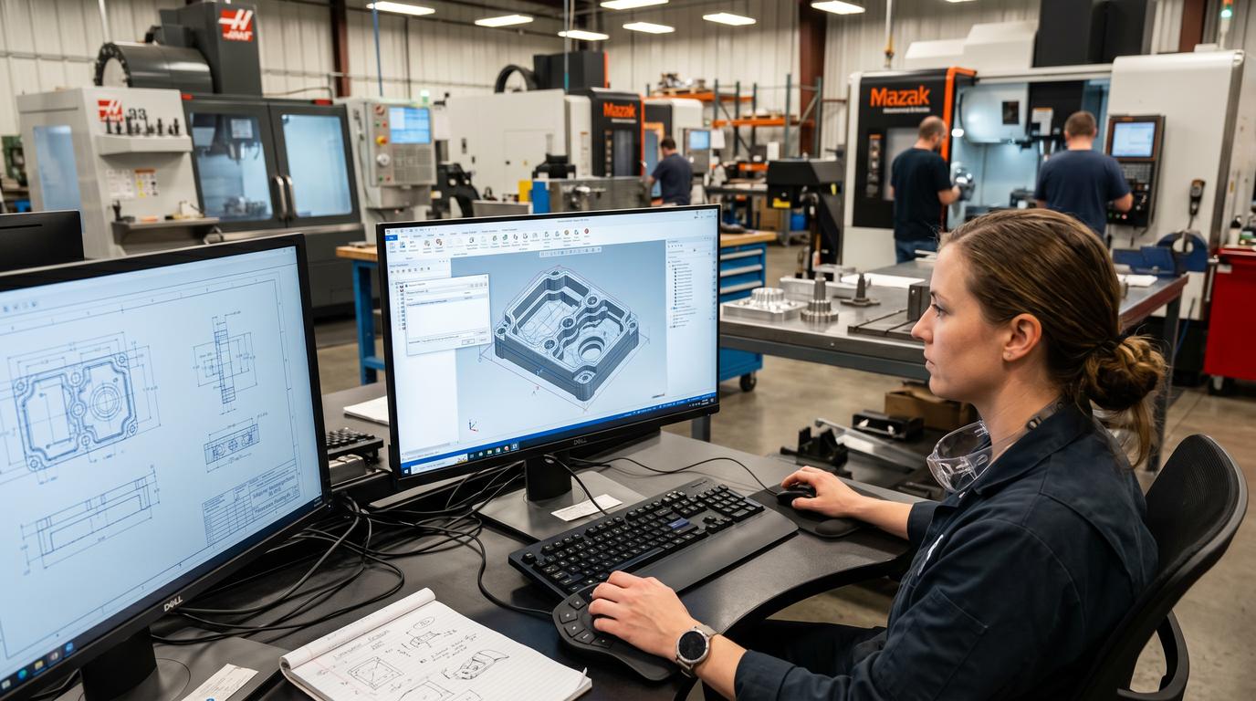
Modern CNC machining relies heavily on digital manufacturing data.
Yet many customers still provide only PDF drawings.
Why PDF Alone Causes Problems
PDF drawings communicate dimensions effectively, but CNC programmers cannot directly generate machining paths from them.
This creates unnecessary engineering work.
The Best RFQ Package
For most CNC projects, suppliers prefer both 2D and 3D files.
Recommended RFQ Package
| File Type | Purpose |
|---|---|
| PDF Drawing | Manufacturing requirements |
| STEP File | CNC programming |
| BOM | Material identification |
| Assembly Drawing | Fit verification |
| Inspection Standard | Quality control |
Providing both formats typically accelerates quoting and reduces manufacturing risk.
Mistake #8: Designing Features That Are Difficult to Machine
Not every CAD feature is practical for CNC machining.
Some designs may be technically possible but extremely expensive.
Deep Narrow Pockets
Deep pockets require long cutting tools.
Long tools increase:
- Tool deflection
- Vibration
- Cycle time
Thin Walls
Thin walls frequently deform during machining.
This can lead to dimensional instability and scrap.
Sharp Internal Corners
A cutting tool is round.
Internal corners cannot be perfectly sharp unless special processes are used.
Adding appropriate corner radii often reduces machining cost significantly.
CNC Drawing Checklist Before Sending an RFQ
Before submitting your next RFQ, review the following checklist.
CNC Drawing Review Checklist
| Item | Status |
|---|---|
| Material grade specified | ✓ |
| Heat treatment defined | ✓ |
| Dimensions complete | ✓ |
| Critical tolerances identified | ✓ |
| Surface finish specified | ✓ |
| Thread details complete | ✓ |
| Revision updated | ✓ |
| Quantity included | ✓ |
| STEP file attached | ✓ |
| Inspection requirements defined | ✓ |
This simple checklist can eliminate many common quotation and production issues.
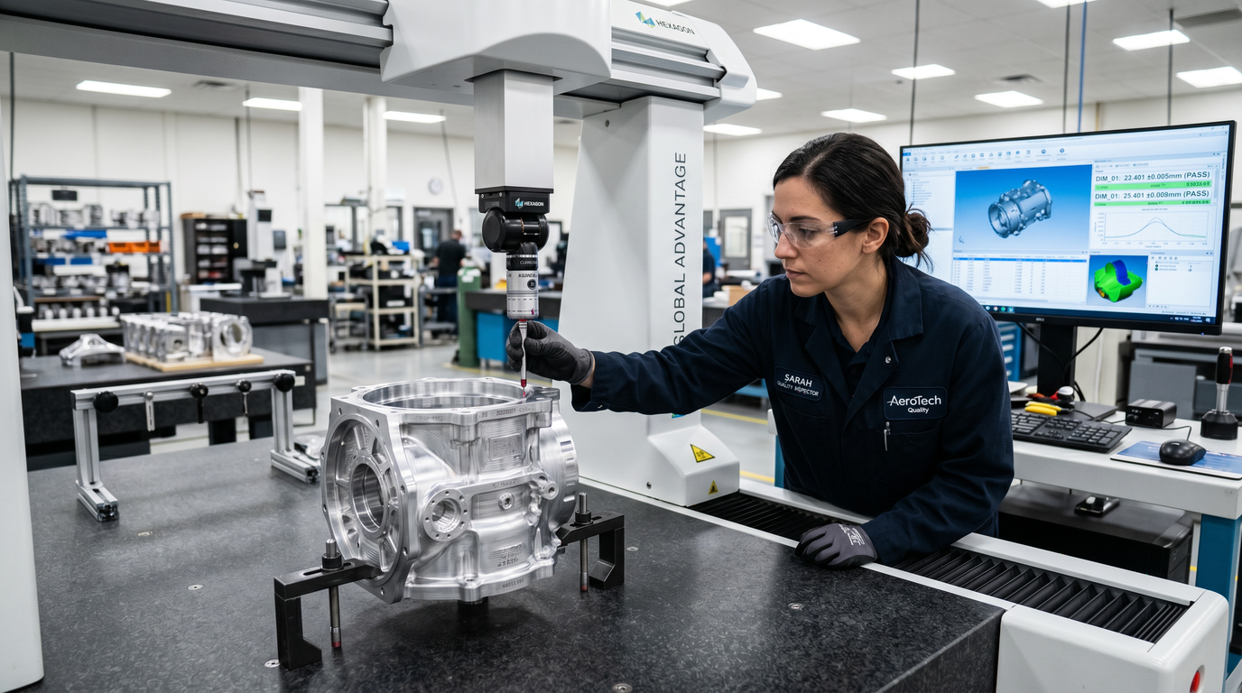
How Suppliers Review Drawings Before Quoting
At Kachi Precision Manufacturing, every drawing undergoes an engineering review before quotation.
Our team typically evaluates:
- Material selection
- Manufacturability
- Tool accessibility
- Tolerance requirements
- Surface finish expectations
- Inspection complexity
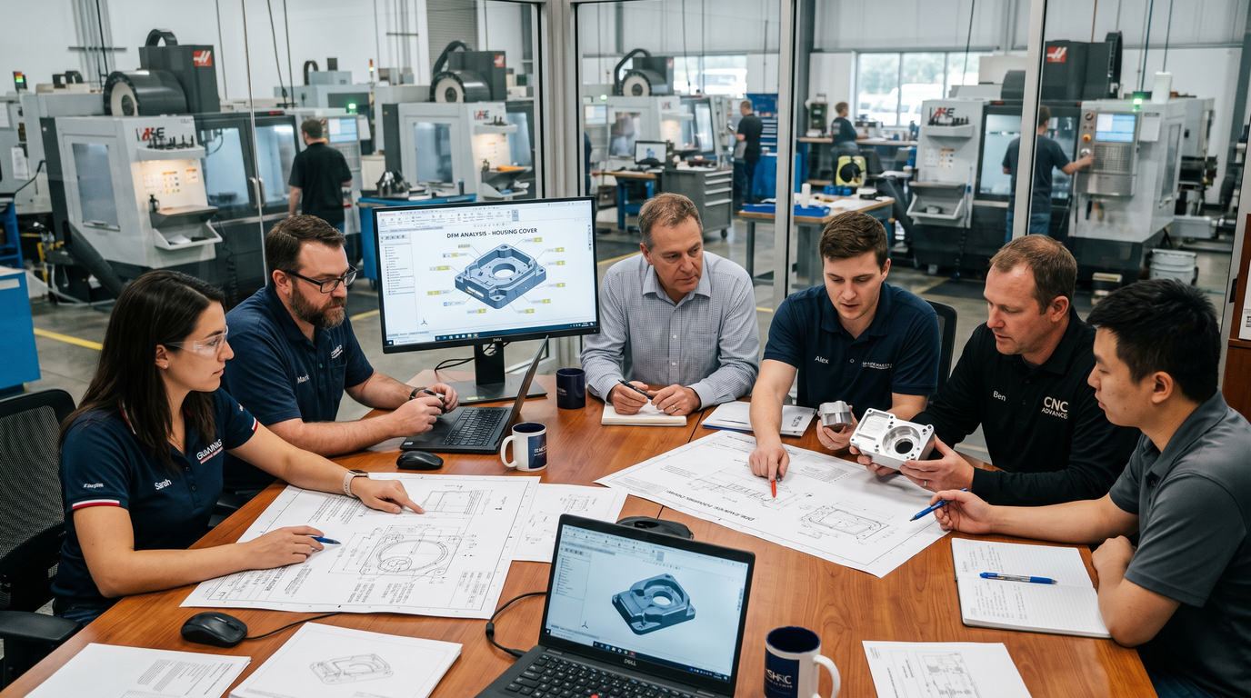
In many cases, small design adjustments can significantly reduce manufacturing costs without affecting part performance.
This is why DFM review remains one of the most valuable services a CNC supplier can provide.
Conclusion
Most machining problems do not originate on the shop floor.
They begin on the drawing.
Clear, practical, and manufacturing-friendly drawings help suppliers quote faster, machine more efficiently, and deliver more consistent quality.
The best drawings are not necessarily the most detailed.
They are the easiest to understand.
Before sending your next RFQ, spend a few extra minutes reviewing your documentation. A small improvement in drawing quality can save days of communication, reduce production costs, and prevent expensive manufacturing mistakes.
FAQ
What information should a CNC drawing include?
A complete CNC drawing should include dimensions, tolerances, material specifications, surface finish requirements, revision information, quantity, and inspection requirements.
What file format is best for CNC machining?
The ideal combination is a PDF drawing and a STEP file. Together they provide both manufacturing requirements and accurate 3D geometry.
Why do tight tolerances increase machining costs?
Tighter tolerances require additional setup, slower machining speeds, more inspections, and increased manufacturing risk.
Should I provide both 2D and 3D files?
Yes. Providing both significantly improves quotation accuracy and reduces interpretation errors.
How can I improve my CNC drawing before RFQ?
Review material specifications, tolerances, surface finish requirements, thread details, and ensure all critical dimensions are fully defined before submission.
Need a Professional CNC Drawing Review?
At Kachi Precision Manufacturing, our engineering team helps customers identify drawing issues before production begins.
We provide DFM analysis, tolerance optimization, material recommendations, and cost-reduction suggestions to help ensure a smoother manufacturing process.
Whether you’re developing prototypes or preparing for production, send us your drawings today for a free engineering review and fast quotation.
Post time: Jun-05-2026


