

Introduction
If you’ve ever sent a CNC machining RFQ and received questions like:
- “What thread class do you need?”
- “Is this a blind hole or a through hole?”
- “Can you confirm the thread depth?”
you’re not alone.
Threaded holes are among the most common features found on machined components, yet they are also one of the most frequent sources of quotation delays and manufacturing errors. A drawing that simply labels a hole as “M8″ without defining the pitch, thread depth, or hole type leaves too much room for interpretation. Suppliers are forced to make assumptions—or pause the quotation process until the missing information is clarified.
The result is often longer lead times, engineering revisions, unexpected costs, and in some cases, parts that cannot be assembled correctly.
In this guide, you’ll learn how thread specifications should be shown on CNC drawings, how machining suppliers interpret thread callouts, the most common mistakes engineers make, and practical tips for creating drawings that support accurate quotations and reliable production.
Why Thread Specifications Matter in CNC Machining
Thread specifications do much more than tell a machinist which tap to use. They define how a threaded feature will be manufactured, inspected, and ultimately assembled with mating components.
When thread information is complete, suppliers can:
- Prepare accurate CNC machining quotations
- Select the correct cutting tools and thread gauges
- Program machining operations correctly
- Reduce engineering clarification
- Improve first-pass production quality
- Ensure proper fit during final assembly
Incomplete thread information, on the other hand, increases manufacturing uncertainty. The supplier must either estimate the missing values or request clarification, both of which delay the project.
Reducing Manufacturing Errors
Incorrect thread dimensions are one of the most common causes of rejected machined parts. Missing details such as pitch or thread depth can result in threads that are too shallow, too deep, or incompatible with mating fasteners.
Improving Quotation Accuracy
RFQ engineers evaluate machining time based on thread size, depth, material, and machining method. A complete thread callout allows suppliers to estimate production cost more accurately.
Ensuring Proper Assembly
Even perfectly machined parts become unusable if threaded holes do not match the intended fasteners. Accurate thread specifications prevent assembly issues before production begins.
What Is a Thread Specification?
A complete thread specification typically includes six key elements:
| Element | Description |
|---|---|
| Thread Diameter | Nominal thread size |
| Pitch or TPI | Distance between threads or threads per inch |
| Thread Standard | Metric, UNC, UNF, BSP, NPT, etc. |
| Thread Class | Defines tolerance and fit |
| Thread Direction | Right-hand or left-hand thread |
| Thread Depth | Effective threaded engagement |
Each of these parameters affects machining strategy, inspection methods, and assembly performance.
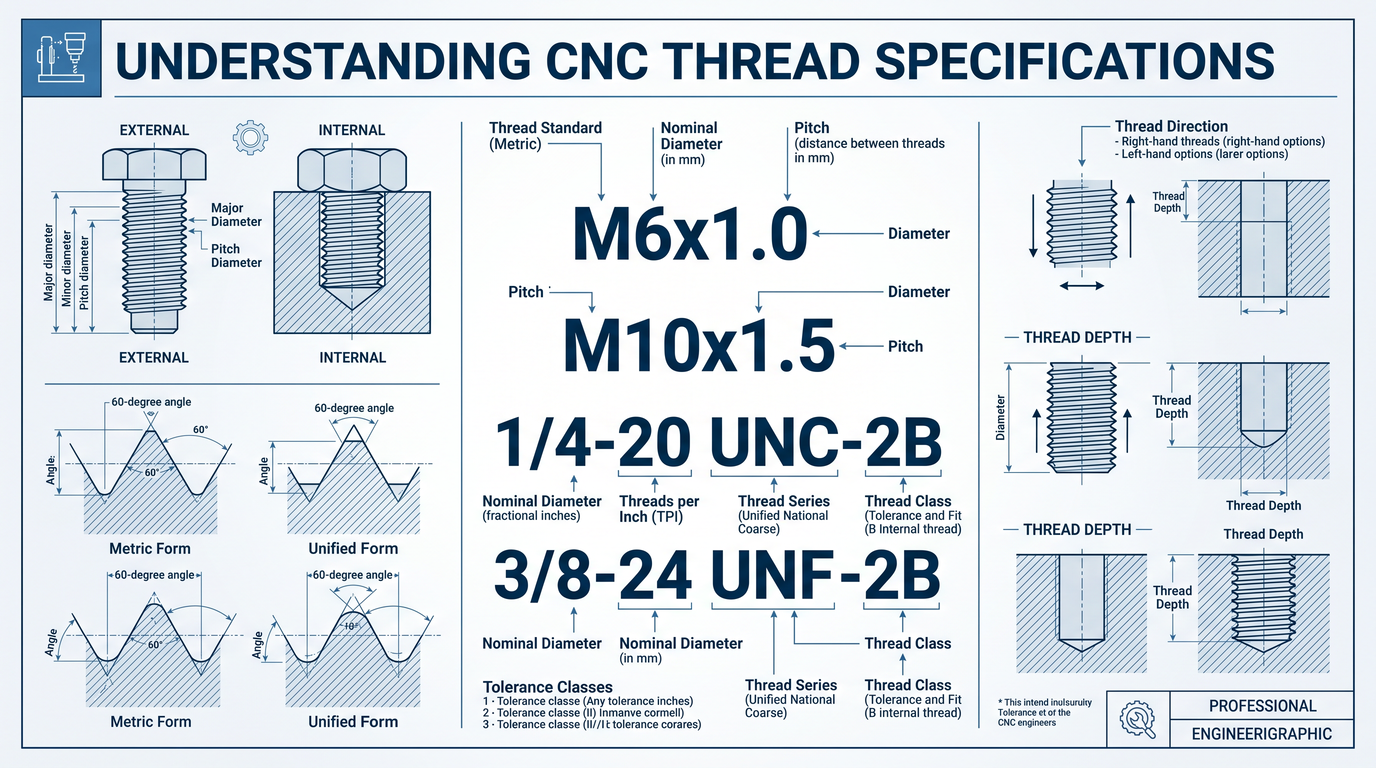
How to Read Metric Thread Callouts
Metric threads are commonly used in Europe, Asia, and many international engineering projects.
Example:
M6 × 1.0This designation can be broken down into three parts:
- M – Metric thread
- 6 – Nominal diameter of 6 mm
- 1.0 – Thread pitch of 1.0 mm
Another example:
M10 × 1.5- Metric thread
- 10 mm diameter
- 1.5 mm pitch
If no pitch is specified, the default coarse pitch is generally assumed. However, engineers should always include the pitch on manufacturing drawings to eliminate ambiguity.
How to Read Imperial Thread Callouts
In North America, Unified threads are commonly specified.
Example:
1/4-20 UNC-2BThis callout contains several pieces of information:
- 1/4 – Nominal diameter
- 20 – Threads per inch (TPI)
- UNC – Unified National Coarse
- 2B – Internal thread tolerance class
Another example:
3/8-24 UNF-2BHere, UNF indicates a finer thread pitch than UNC, offering greater holding strength for applications requiring higher preload.
Metric Threads vs. UNC vs. UNF
Different thread systems are designed for different applications.
| Thread Type | Common Applications | Advantages |
|---|---|---|
| Metric | General machinery, automation, electronics | Global standard, easy specification |
| UNC | Industrial equipment, structural assemblies | Stronger threads, easier assembly |
| UNF | Aerospace, automotive, precision equipment | Better vibration resistance and higher clamping force |
Understanding the required thread standard helps avoid compatibility issues during assembly.
Understanding Thread Depth and Hole Depth
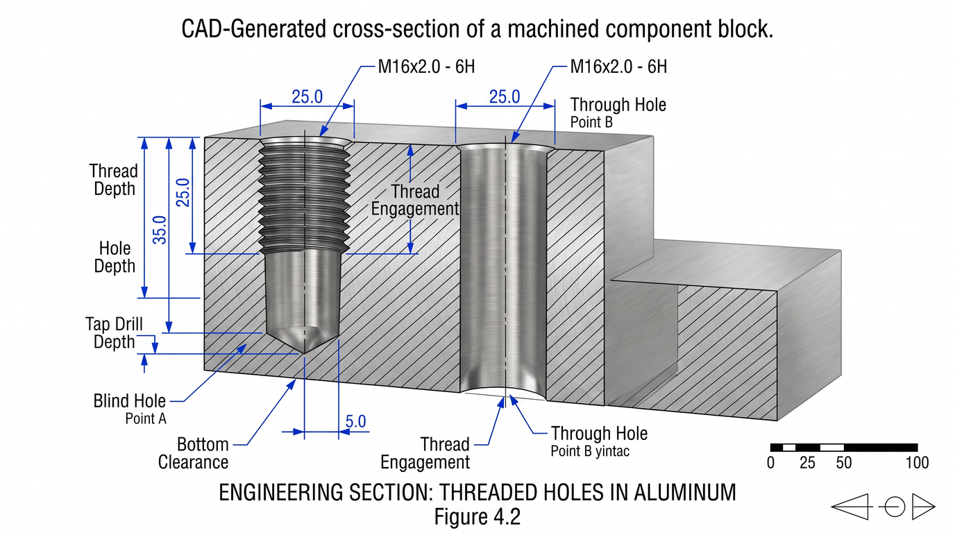
Thread depth and hole depth are often confused, but they are not the same.
Consider this specification:
M8 × 1.25

Thread depth: 12 mm
Hole depth: 16 mm
The hole must always be deeper than the threaded portion to allow for tap runout and chip evacuation during machining.
If only the hole depth is specified, suppliers cannot determine the effective thread engagement.
Blind Holes vs. Through Holes
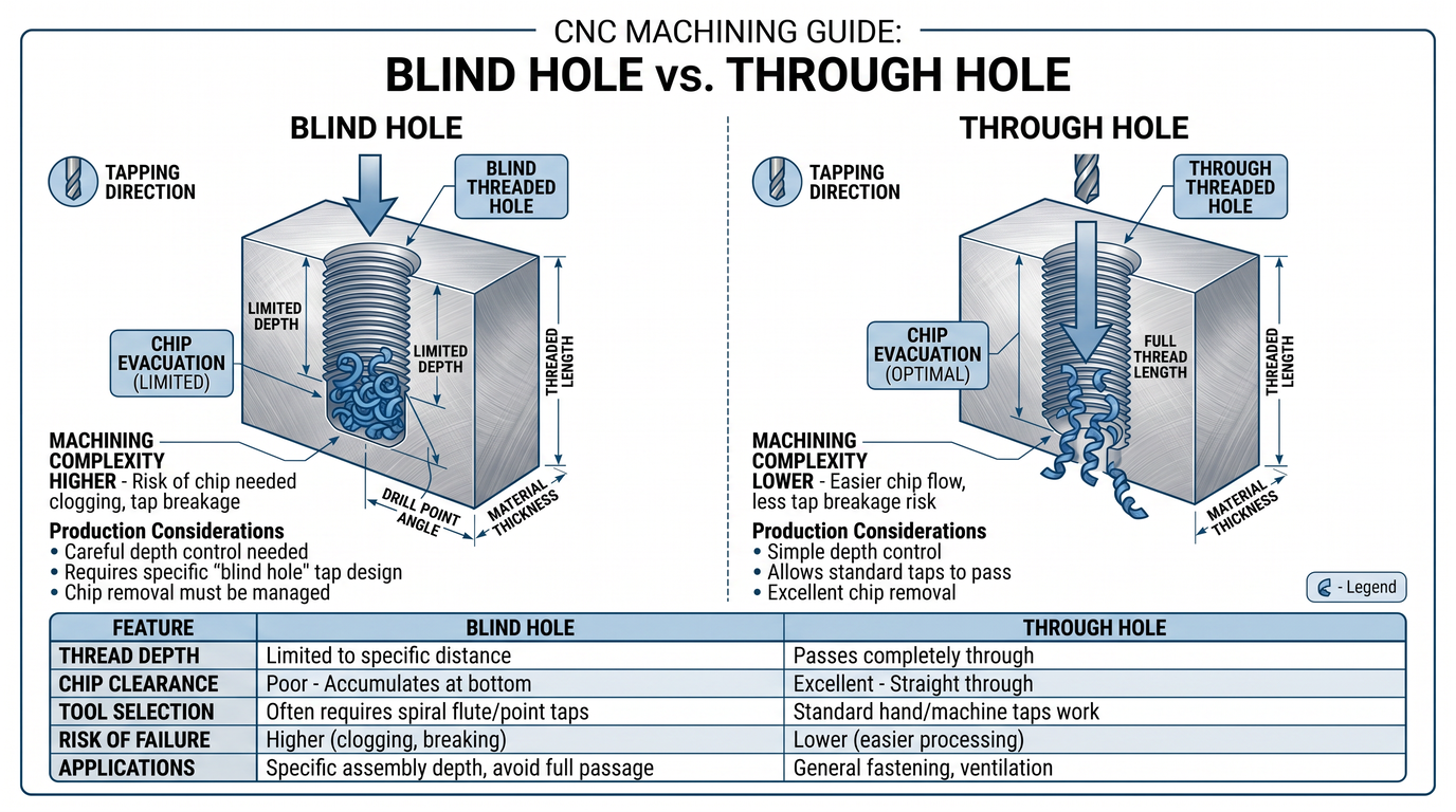
The type of hole also affects machining difficulty and quotation.
Blind Hole
- Does not pass completely through the part
- Requires careful depth control
- More difficult to tap
- Higher machining cost
Through Hole
- Passes completely through the material
- Easier chip evacuation
- Faster machining
- Lower manufacturing cost
Clearly indicating the hole type on drawings prevents programming errors and improves quotation accuracy.
Common Thread Specification Mistakes
Even experienced engineers occasionally overlook important thread details.
The most common issues include:
- Missing thread pitch
- Missing thread depth
- Thread class not specified
- Blind or through hole not identified
- Incorrect thread designation
- Inconsistent thread notes between 2D drawings and 3D models
Each of these omissions can delay the quotation process or result in incorrect machining.
Best Practices for Engineers Creating CNC Drawings
To improve manufacturability and reduce RFQ turnaround time:
- Always specify thread pitch.
- Clearly define thread depth.
- Indicate whether the hole is blind or through.
- Include thread class where applicable.
- Use standardized thread callouts.
- Provide both 2D drawings and STEP files.
- Highlight critical threaded features.
These practices help suppliers quote faster and manufacture parts correctly the first time.
How CNC Suppliers Interpret Thread Drawings
When a supplier receives an RFQ, engineers typically follow a structured review process.
- Review the drawing for complete thread specifications.
- Verify compatibility between 2D drawings and 3D CAD models.
- Select appropriate machining and tapping tools.
- Develop CNC programs.
- Plan inspection using thread gauges or CMM equipment.
- Confirm manufacturability before issuing the quotation.
A well-prepared drawing reduces engineering questions and speeds up every step of this workflow.
How Kachi Precision Reviews Thread Specifications Before Production
At Kachi Precision, every RFQ undergoes an engineering-led drawing review before quotation.
Our process includes:
- DFM analysis of threaded features
- Verification of thread standards and callouts
- Review of thread depth and hole depth
- Confirmation of blind and through holes
- Inspection planning using calibrated thread gauges
- Cross-checking 2D drawings against STEP models
By identifying potential issues before machining begins, we help customers avoid costly revisions, reduce quotation delays, and improve production reliability.
Conclusion
Thread specifications may appear to be a small detail on a CNC drawing, but they have a significant impact on quotation accuracy, machining efficiency, and final assembly quality.
A complete thread callout should always define:
- Thread size
- Pitch or TPI
- Thread standard
- Thread class
- Hole type
- Thread depth
Taking a few extra minutes to prepare clear drawings can save days of engineering clarification and prevent expensive manufacturing errors later.
Whether you’re designing prototypes or preparing production RFQs, accurate thread specifications help ensure smoother communication, faster quotations, and higher-quality machined parts.
FAQ
What is a thread specification?
A thread specification defines the complete dimensions and standards required to manufacture a threaded feature, including diameter, pitch, thread type, class, direction, and depth.
What does M6 × 1.0 mean?
It indicates a metric thread with a 6 mm nominal diameter and a 1.0 mm thread pitch.
What is the difference between UNC and UNF?
UNC (Unified National Coarse) has fewer threads per inch and is commonly used for general industrial applications, while UNF (Unified National Fine) has a finer pitch, providing greater clamping force and vibration resistance.
What is thread depth?
Thread depth refers to the usable length of the threaded portion inside a hole, not the total drilled hole depth.
How should threaded holes be shown on engineering drawings?
Threaded holes should include the thread designation, pitch or TPI, thread class (if required), thread depth, hole type (blind or through), and any special notes needed for manufacturing or inspection.
Post time: Jul-02-2026


